Multi-Sensor Timestamp Synchronization System
A hardware-software synchronization stack that aligns stereo thermal cameras, IMU, radar, and robot data through PTP network time, MCU-generated trigger pulses, and driver-level timestamp assignment for repeatable multi-sensor data collection.
Overview
A hardware-software synchronization stack that aligns stereo thermal cameras, IMU, radar, and robot data through PTP network time, MCU-generated trigger pulses, and driver-level timestamp assignment for repeatable multi-sensor data collection.
Details
Overview
Reliable multi-sensor fusion starts before the estimator: every thermal image, IMU sample, radar frame, and robot state has to refer to the same time base. This project builds that infrastructure as a hardware-software synchronization stack for the fireground robotics payload. It combines PTP network time, MCU-generated trigger pulses, UDP timestamp distribution, and driver-level timestamp assignment so that the recorded data streams are sensor-fusion ready.
The result is a practical synchronization platform for field-style robot sensing experiments. Instead of relying only on PC receive time or approximate software synchronization, the stack ties physical trigger events to a network-synchronized clock and propagates that timestamp into the camera and IMU data paths.
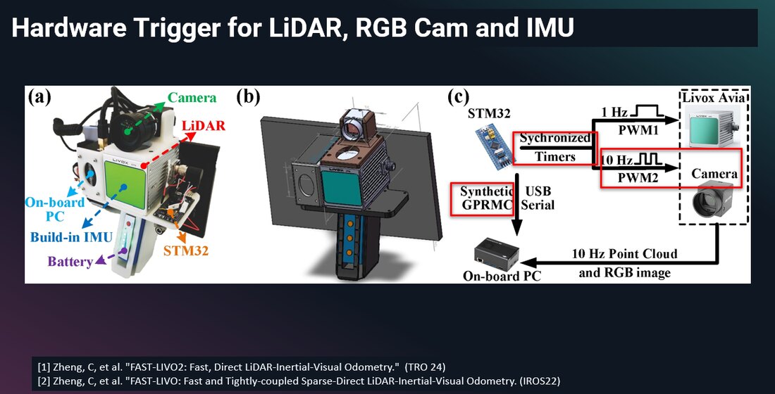
Why Custom Synchronization Was Needed
Existing LiDAR-camera trigger references are useful for understanding hardware triggering, but they do not directly cover this payload. The fireground system has stereo thermal cameras, high-rate inertial data, radar, robot telemetry, and PTP-capable network devices, all of which have different timing interfaces and transport delays. A direct copy of a LiDAR-RGB trigger layout would still leave unresolved timestamp assignment and driver integration problems.
Network Time and Trigger Distribution
The system separates clock alignment from exposure triggering. A mini-PC acts as the PTP time source, while PTP-aware devices and the MCU synchronize to the same network clock. The MCU then generates physical trigger pulses for hard-synchronized sensors and broadcasts the corresponding PTP timestamp to the computer, where a software bridge distributes the event to sensor drivers.
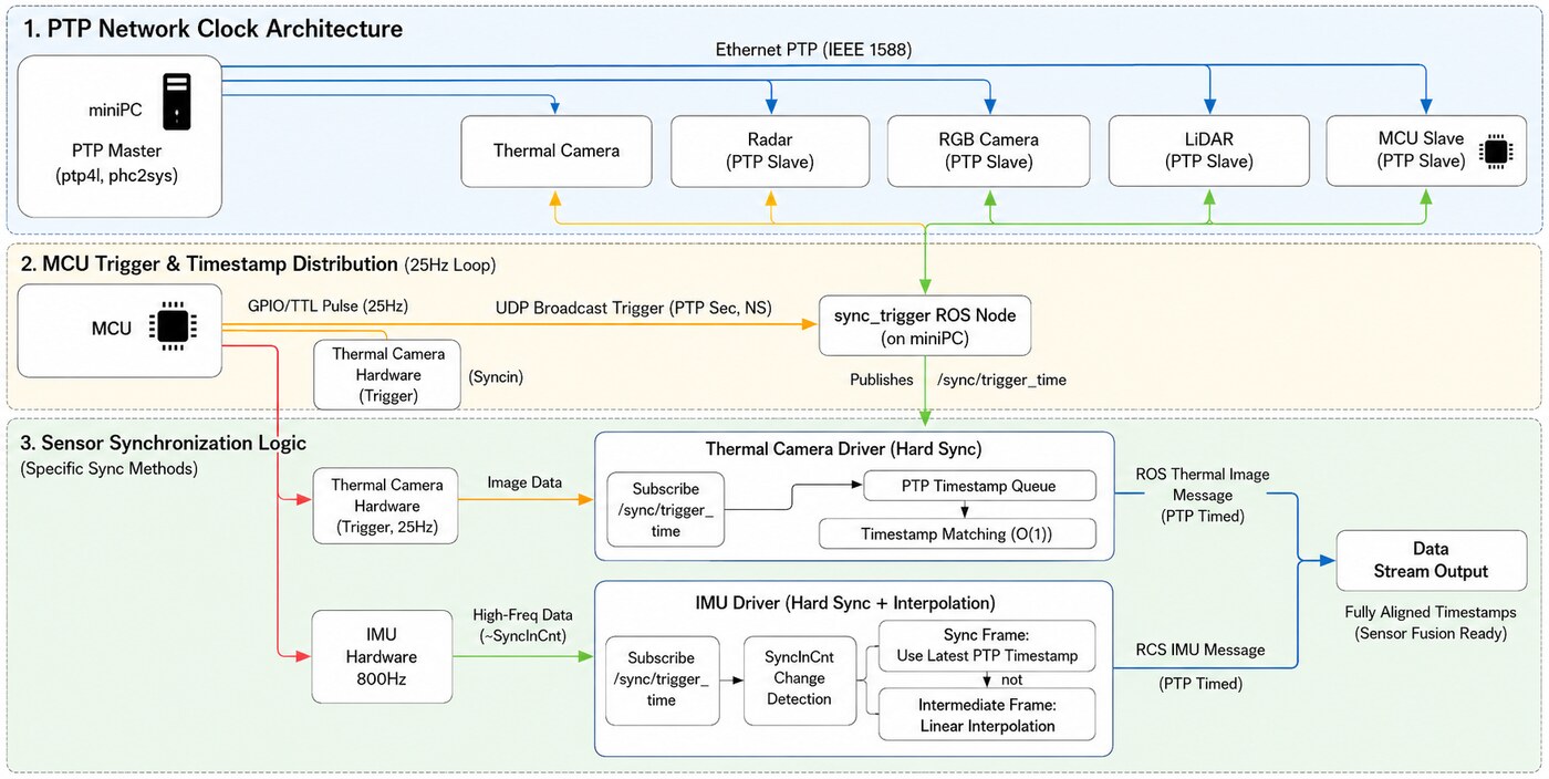
This design gives each sensor the synchronization path it can actually support. Cameras can use hardware trigger pins for exposure timing. The IMU can use SyncIn count changes and interpolation against trigger events. PTP-capable devices can remain aligned through the network clock. The software layer then converts these heterogeneous timing signals into consistent ROS message timestamps.
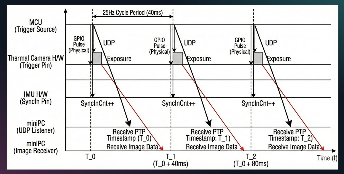
Timing Logic
The timing path is built around the trigger event rather than the data arrival event. On each 25 Hz cycle, the MCU emits a hardware pulse and sends the PTP timestamp of that trigger. Image data may arrive later because of exposure and transport delay, but the driver can stamp the image with the trigger time rather than the PC receive time. For high-rate IMU data, trigger counts define synchronization frames and intermediate samples are assigned by interpolation.
Embedded Trigger Hardware
The embedded side is implemented on an STM32H743-class Ethernet MCU board. The firmware combines PTP/gPTP synchronization, GPIO trigger generation, UDP event broadcast, and persistent network configuration. The board acts as a bridge between the network clock and electrical trigger interfaces, making the timing system deployable with the robot payload rather than only on a lab bench.

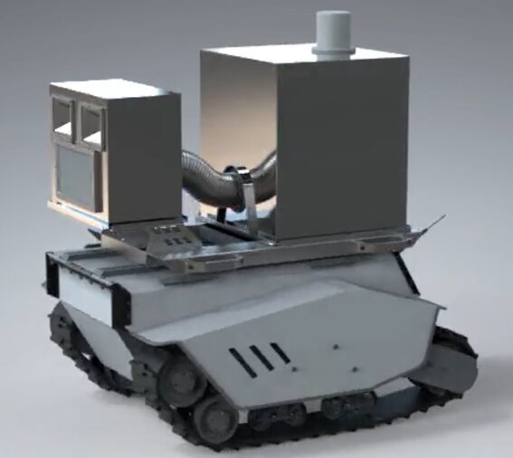
Payload Integration
The synchronization stack is designed around the mobile fireground sensing platform, not as a standalone timing demo. The same payload carries the sensing, compute, thermal protection, and robot interface needed for field data collection. By aligning timestamps at the acquisition level, the system makes multi-sensor experiments easier to replay, compare, and debug.

The implementation spans embedded firmware, a trigger-event bridge, and adapted sensor drivers for the thermal cameras and IMU. The important contribution is the system boundary: hardware timing, network time, and software timestamps are treated as one pipeline, so the recorded sensor streams are aligned at acquisition time rather than patched afterward.